
Automotive manufacturing is one of the most demanding environments for industrial lighting. Assembly lines run 24 hours a day. Workers perform precision tasks where a missed weld seam or improperly torqued fastener can result in a recall costing tens of millions of dollars. Automated optical inspection (AOI) systems require consistent, flicker-free illumination to detect sub-millimeter defects. Paint booths demand accurate color rendering so finish teams can identify orange peel, fisheye, and metallic flake alignment under conditions that match showroom lighting.
Legacy metal halide and fluorescent systems were never designed with these requirements in mind. They flicker at 100-120 Hz, run hot, take 15-20 minutes to restrike after a shutdown, and deliver inconsistent color temperatures that shift as the lamp ages. Modern LED fixtures eliminate every one of those problems — but only when specified correctly for each zone inside a typical automotive plant.
This guide covers everything a lighting engineer, plant manager, or facilities director needs to know: illuminance standards by zone, fixture selection criteria, controls integration, compliance requirements, and a real-world ROI model for a mid-size body-in-white (BIW) facility.
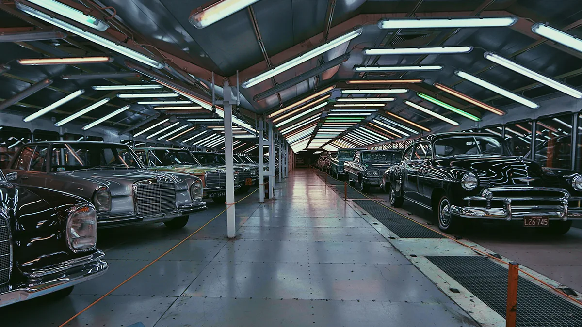
Why Automotive Plants Are a Special Case for Industrial Lighting
Most industrial lighting guides treat factories as a single uniform environment. Automotive plants are the opposite — a collection of radically different micro-environments packed into a single building, each with distinct photometric requirements.
Zone-by-Zone Illuminance Demands
The table below summarizes IES RP-7 (Manufacturing) and IES RP-20 requirements alongside automotive-specific best practices from OEM supplier quality programs such as AIAG CQI-9 (heat treatment), CQI-11 (plating), and general assembly guidance from Tier 1 supplier audits.
| Zone | Recommended Illuminance (fc) | Min CRI | CCT | Notes |
|---|---|---|---|---|
| Stamping / Press Shop | 50-75 | 70 | 5000K | High-bay, machine guarding shadows critical |
| Body-in-White (BIW) Weld | 75-100 | 80 | 5000K | Robotic cells need uniform background for vision systems |
| Paint Prep / Body Shop | 100-150 | 90+ | 5000K–6500K | Surface inspection requires daylight-spectrum light |
| Paint Booth Interior | 100-200 | 95+ | 6000K–6500K | Explosion-proof fixtures required (Class I Div 1 or Zone 1) |
| Final Assembly Line | 75-100 | 85+ | 5000K | Vertical surfaces (doors, dashboards) need adequate illuminance |
| Trim & Chassis Line | 75-100 | 80 | 5000K | Overhead + supplemental task lighting recommended |
| Quality Inspection | 150-300 | 95+ | 5000K–6500K | Simulated daylight critical for color matching |
| AOI / Vision Systems | Varies (see below) | N/A | Machine-specified | Flicker-free (<1% SVM), stable color point essential |
| Engine / Powertrain Test | 75-100 | 80 | 5000K | High vibration environment, impact-resistant lenses |
| Parts Storage / Lineside | 30-50 | 70 | 4000K–5000K | Standard high-bay, motion control acceptable |
The Flicker Problem in Automated Vision Systems
This is the single most underappreciated lighting issue in modern automotive plants. AOI systems use high-speed cameras — commonly running at 500-2000 frames per second — to inspect welds, fastener torque markings, adhesive bead profiles, and surface finish. When ambient lighting flickers even slightly, camera frames alternate between bright and dim, creating false-negative and false-positive defect signals.
LED drivers rated to Stroboscopic Visibility Measure (SVM) below 0.4 (IEC TR 61547-1) are the only safe choice in robotic cells with integrated vision. Standard LED drivers with basic PWM dimming can exhibit SVM values of 1.5 to 3.0 at partial loads — well above the threshold where camera artifacts appear. Always request the driver’s SVM specification at 100%, 75%, and 50% load before specifying AOI zone fixtures.
Fixture Selection by Zone
High-Bay Fixtures: Press Shop, BIW, Powertrain
UFO high-bay and linear high-bay LED fixtures are the workhorses of main production floor areas in automotive plants. Key selection criteria for this environment:
- Lumen output: 40,000-80,000 lm per fixture for ceilings of 25-45 ft (7.6-13.7 m). Use a photometric layout tool (AGi32, DIALux, or Relux) to confirm point-by-point illuminance rather than relying on fixture-count rules of thumb.
- Color temperature: 5000K is the automotive industry standard for assembly. It maximizes contrast for visual inspection and aligns with OSHA guidance on alertness in shift-work environments.
- IP rating: IP65 minimum in stamping and BIW areas where coolant mist and metal shavings are present. IP66 near wash-down areas.
- Vibration resistance: IEC 60068-2-6 test certification for fixtures above large presses or stamping lines — vibration will work loose any fixture that relies on friction alone for driver retention.
- Driver SVM: <0.4 if the zone is adjacent to robot cells. Even in non-AOI zones, <1.0 SVM is best practice for ergonomic compliance (IEEE Std 1789-2015).
- Dimming protocol: 0-10V or DALI-2 for integration with plant-wide controls. Wireless 5-button override at each fixture grouping for maintenance access.
Paint Booth: Explosion-Proof LED
Paint booths in automotive facilities are Class I, Division 1 hazardous locations (NEC Article 511 / ATEX Zone 1) due to the continuous presence of flammable solvent vapors during spray operations. This is a non-negotiable electrical code requirement — standard LED fixtures are prohibited inside spray booths regardless of IP rating.
Automotive paint booth LED specifications should include:
- Hazardous location listing: UL 844 Class I Div 1, Groups C & D (for most automotive paint solvent formulations). ATEX II 2G Ex d IIC T4 for facilities following EU standards.
- CRI 95+ / R9 > 85: Paint color accuracy requires near-daylight rendering. Standard CRI 80 fixtures will create metamerism failures where colors appear correct under booth lighting but shift under showroom conditions.
- CCT 6000-6500K: Mimics D65 daylight reference — the standard used in automotive color approval processes (SAE J1545, CIE 015).
- Luminance uniformity: Booth-wide uniformity ratio (minimum:average) should not exceed 1:3. Darker pockets create missed defect zones. Photometric modeling is mandatory at specification stage.
- Surface temperature: T-class rating must be below the autoignition temperature of the lowest-AIT solvent in use. For typical polyurethane clears, T3 (200°C) provides adequate margin.
Quality Inspection Stations: High-CRI Task Lighting
Final inspection bays need two illumination systems: ambient high-bay lighting at 100-150 fc and dedicated inspection luminaires that can achieve 200-300 fc at the inspection surface. Typical automotive QC inspection light specifications:
- CRI 97+, R9 > 95: The highest color rendering available in production LED products. Critical for metallic paint, chrome, and plastic trim color acceptance.
- Paired CCT sources: Quality labs often install paired 5000K (D50) and 6500K (D65) sources to evaluate color under different viewing conditions — the same practice used in light booths for material approval.
- Glare control: UGR <16 at inspection stations. Glare causes pupillary constriction that reduces inspector sensitivity to surface defects. Deep-cell louvers or micro-lens optics achieve this while maintaining adequate illuminance levels.
- Vertical illuminance: Door opening inspection and glass inspection require adequate vertical illuminance (not just horizontal). Target 75 fc vertical at the inspection point, not just overhead. LED track lighting or wall-mounted arrays achieve this where ceiling pendants cannot.
Lineside Parts Racks and Kanban Areas
Parts sequencing racks and kanban supermarkets adjacent to the assembly line are often overlooked in lighting design. Pickers working these areas make high-frequency part identification decisions — errors in part selection create upstream quality defects that may not surface until final inspection or, worse, field service.
Effective lineside lighting uses a two-layer approach: 50 fc ambient from ceiling-mounted LED strips (4000K or 5000K) supplemented by shelf-level LED strip lighting at 50-75 additional fc. Shelf LEDs positioned at the front lip of each rack level ensure vertical face illumination of bins and kanban cards, dramatically improving part number legibility and reducing mis-picks.
Controls Integration in Automotive Plants
Automotive plants present unique controls challenges compared to generic industrial facilities: multiple production zones with different shift patterns, frequent equipment layout changes (model changeovers every 2-4 years), and tight integration requirements with Manufacturing Execution Systems (MES) and Building Automation Systems (BAS).
Zone-Based Lighting Control Strategy
A practical automotive plant controls architecture divides the facility into three tiers:
- Tier 1 — Production zones: Fixtures on DALI-2 or 0-10V, addressable by production zone. Scene control from MES: ramp to 100% at shift start, hold at 100% during production, dim to 30% during planned breaks, off during extended shutdowns. Manual override at zone panel for maintenance.
- Tier 2 — Non-production support: Parts racks, tool cribs, break rooms, offices adjacent to production. Occupancy sensors with 15-minute timeout, daylight harvesting where skylights exist. Estimated 40-60% additional energy reduction vs. always-on strategy in Tier 1.
- Tier 3 — Perimeter and security: Parking lots, dock doors, exterior walls. Photocell + motion sensor control, maintained at 30% overnight security level, 100% when motion detected. Full-cutoff dark-sky fixtures prevent light trespass to adjacent residential zones (common in suburban automotive campuses).
Protocol Selection: DALI-2 vs. 0-10V vs. Wireless
For automotive plants specifically:
- DALI-2: Best choice for BIW, final assembly, and quality inspection zones. Two-way communication enables driver-level fault reporting (lamp failure, over-temperature) directly to maintenance management systems. Individual fixture addressability supports flexible zone re-grouping during model changeovers without rewiring.
- 0-10V: Acceptable for stamping and press areas where zone counts are small and re-grouping is infrequent. Lower installed cost. No fault feedback.
- Wireless Mesh (Zigbee 3.0 / Thread): Viable for parts storage, lineside racks, and areas where conduit routing is difficult. Not recommended for AOI-adjacent zones due to wireless interference risk with machine vision systems (though RF interference with industrial cameras is typically in different frequency bands, conservative system integrators prefer wired control in those areas).
Energy Code and Certification Requirements
Automotive plants are large energy consumers — a typical 1-million-square-foot facility may carry 3-8 MW of lighting load. This scale puts automotive lighting upgrades in scope for multiple regulatory and incentive frameworks:
DLC Premium Listing
DesignLights Consortium (DLC) Premium listing is required to qualify for most utility rebate programs in North America. For automotive high-bay fixtures, DLC Premium requires a minimum efficacy of 150 lm/W and SVM < 0.4 — the latter requirement aligns perfectly with automotive AOI zone demands. Specifying DLC Premium fixtures across the entire facility ensures maximum rebate eligibility without zone-by-zone compliance review.
ASHRAE 90.1 Compliance
ASHRAE 90.1-2022 sets Lighting Power Density (LPD) limits for manufacturing facilities at 0.50-0.80 W/sqft depending on task. LED retrofits routinely achieve 0.20-0.35 W/sqft in automotive production zones — well below the code limit, which provides flexibility in design and serves as documentation for Authority Having Jurisdiction (AHJ) plan reviews.
ISO 14001 and Sustainability Reporting
All major automotive OEMs now require Tier 1 and Tier 2 suppliers to report Scope 1 and Scope 2 carbon emissions under frameworks like CDP (formerly Carbon Disclosure Project) and GHG Protocol. LED lighting upgrades produce measurable Scope 2 reductions that feed directly into annual sustainability reports. For a 500,000 sqft plant reducing lighting energy by 65%, the annual CO₂ reduction (at US average grid intensity of 0.386 kg CO₂/kWh) is typically 1,200-2,000 tonnes — meaningful at the facility reporting level.
ROI Case Study: Mid-Size Body-in-White Facility
The following model is based on a 600,000-square-foot BIW stamping and welding facility with 18-meter ceiling height in the main production hall, 8-meter ceiling in subassembly, and ground-level quality inspection stations.
| Parameter | Before (Metal Halide + T8 Fluorescent) | After (LED Upgrade) |
|---|---|---|
| Total installed wattage | 2,840 kW | 890 kW |
| Annual lighting energy (8,500 hrs) | 24,140,000 kWh | 7,565,000 kWh |
| Annual energy cost ($0.085/kWh) | $2,051,900 | $643,025 |
| Annual maintenance (lamp replacement, labor) | $186,000 | $22,000 |
| Total annual cost | $2,237,900 | $665,025 |
| Annual savings | $1,572,875 | |
| Project cost (installed) | $3,200,000 | |
| Utility rebates (estimated) | -$480,000 | |
| Net project cost | $2,720,000 | |
| Simple payback | 1.73 years | |
| 10-year NPV (7% discount rate) | $7,600,000 | |
Note: The above does not include production quality improvements. Automotive OEMs that have tracked defect escape rates before and after LED upgrades in final inspection zones consistently report 8-15% reductions in cosmetic defect escapes — a benefit that dwarfs the energy savings in dollar terms.
Implementation Roadmap for Automotive Facilities
Phase 1: Baseline Assessment (Weeks 1-4)
Conduct a zone-by-zone photometric survey using a calibrated lux meter (at least Class C per ISO/CIE 19476). Record existing fixture inventory, wattage, remaining useful life, and current illuminance levels. Map AOI system locations and identify flicker-sensitive zones. Gather 12 months of energy billing data from the utility account for baseline energy model.
Phase 2: Photometric Design and Fixture Specification (Weeks 5-8)
Develop zone-by-zone lighting designs using photometric software. Ensure point-by-point illuminance plots meet IES RP-7 minimums and automotive zone-specific requirements above. Confirm fixture dimensions fit within existing mounting locations to minimize structural modifications. Validate DLC Premium listing for all products. Request SVM specifications at full and partial load for any AOI-adjacent fixture.
Phase 3: Controls System Architecture (Weeks 6-10)
Define lighting control zones aligned with production area boundaries and MES zones. Design DALI-2 bus topology (maximum 64 devices per bus, up to 64 buses per controller for large facilities). Identify integration points with existing BAS (typically BACnet/IP or Modbus TCP). Design network infrastructure for wireless zones. Coordinate with IT security team — lighting controls networks should be on isolated VLANs.
Phase 4: Installation — Phased by Zone
Automotive plants cannot afford production shutdowns for lighting upgrades. A zone-by-zone installation approach — aligning retrofit work with planned weekend or model changeover shutdowns — is standard practice. Typical sequencing: parts storage and support areas first (no production impact), then non-robot BIW zones (one aisle at a time during weekend partial shutdowns), then AOI and vision system zones (coordinated with robot maintenance windows), then paint booth last (requires full booth shutdown and VOC compliance testing before restart).
Phase 5: Commissioning and Verification
Post-installation verification should include: point-by-point illuminance measurements matching the photometric design (within ±10%), SVM verification in AOI zones using a flicker meter, DALI-2 commissioning report from the controls vendor, and a 30-day energy monitoring period to validate modeled savings. Any zone failing to meet illuminance targets should be corrected before final acceptance.
Common Specification Mistakes in Automotive Lighting Projects
- Specifying standard LED in paint booths: The most dangerous mistake. Non-explosion-proof fixtures in Class I Div 1 locations create code violations, insurance voids, and genuine fire risk. Always verify hazardous location listing before approving submittals.
- Ignoring SVM in robot cells: Purchasing teams often substitute lower-cost drivers that meet efficacy specs but lack SVM documentation. Machine vision false-rejection rates may increase by 5-20%, causing line stoppages that cost far more than the driver upgrade differential.
- Over-relying on raw lumen numbers for paint booths: A 200-watt fixture with 30,000 lm and CRI 80 is useless in a paint booth. Specify CRI and CCT in the RFQ alongside lumen output — they are equally important.
- Uniform CCT across all zones: Stamping floors and final inspection areas have different requirements. A single CCT specification optimized for one zone will compromise another. Zone-differentiated CCT specifications are worth the minor added procurement complexity.
- Skipping photometric modeling: Automotive facilities have complex obstruction patterns from overhead conveyors, robot frames, and mezzanines. Point-by-point modeling that accounts for these obstructions is the only reliable way to confirm adequate illuminance — fixture-count rules of thumb routinely miss dark zones near obstructions.
Internal Resources
For related guides that complement automotive lighting design, see our articles on explosion-proof LED lighting (covering NEC Article 511 paint booth requirements in detail), industrial LED lighting design and layout (photometric calculation methods), LED dimming systems and controls (DALI-2 and 0-10V protocol deep-dive), and our factory lighting energy efficiency audit guide (baseline assessment methodology).
Frequently Asked Questions
What CRI is required for automotive paint booth LED lighting?
A minimum CRI of 95 with R9 above 85 is the practical standard for automotive paint booths. OEM color approval processes reference D65 daylight (6500K) illumination, and lower CRI sources create metamerism — colors that match under booth lighting but shift under showroom or daylight conditions. For critical metallic and pearl finishes, CRI 97+ is increasingly specified.
Do I need explosion-proof LED fixtures in my paint booth?
Yes. Automotive paint booths are classified as Class I, Division 1, Group C & D hazardous locations under NEC Article 511. Standard LED fixtures — regardless of their IP rating — are not approved for use in these areas. You need fixtures with UL 844 listing for the specific hazardous location classification of your booth. This is an electrical code requirement, not an optional upgrade.
What SVM value should I specify for robot cells and AOI zones?
Specify SVM < 0.4 (per IEC TR 61547-1) at all dimming levels used during production — not just at 100%. Many drivers with acceptable full-load SVM exhibit high flicker at 50-75% load if they use basic PWM dimming. Request SVM test data at 100%, 75%, and 50% load from the driver manufacturer before approving submittals for AOI-adjacent zones.
How much energy can a typical automotive plant save by switching to LED?
A well-designed LED retrofit in an automotive facility typically reduces lighting energy consumption by 60-70% compared to metal halide and T8 fluorescent systems. For a 500,000 sqft plant running three shifts, this commonly translates to $700,000-$1,500,000 in annual energy savings depending on local utility rates. Maintenance cost reductions add another $100,000-$250,000 per year. Payback periods of 1.5-2.5 years are common when utility rebates are applied.
What color temperature is recommended for automotive assembly lines?
5000K is the industry standard for automotive assembly and inspection. It provides maximum contrast for visual inspection tasks, supports alertness in three-shift environments, and aligns with OSHA recommendations for shift-work facilities. Lower CCTs (3000K-4000K) are appropriate only in non-critical support areas like locker rooms and offices. Quality inspection stations may benefit from paired 5000K and 6500K sources to evaluate color under multiple conditions.
Can I phase the LED retrofit to avoid production shutdowns?
Yes — phased zone-by-zone installation is the standard approach for automotive facilities. Work in support areas and parts storage first (no production impact), then production zones during planned weekend or model changeover shutdowns. Paint booth retrofits require full booth shutdowns coordinated with maintenance windows. A well-planned phased approach for a 500,000 sqft facility typically completes over 6-12 months with no unplanned downtime.
How do LED upgrades support our ISO 14001 and CDP reporting?
LED lighting upgrades generate measurable Scope 2 carbon emissions reductions that feed directly into ISO 14001 environmental management objectives and CDP disclosure reports. For a typical automotive plant reducing lighting energy by 65%, the annual CO₂ reduction is 1,200-2,500 tonnes at US average grid intensity. Document pre- and post-installation energy consumption through utility billing data and sub-metered lighting circuits for auditable emissions reporting.