
Walk into a freshly retrofitted factory and you’ll sometimes find workers shading their eyes with their hands — not because the floor is too dark, but because the lights are too harsh. Glare is one of the most under-addressed problems in industrial lighting upgrades, and it costs more than people realize: reduced visual acuity, slower task completion, eye fatigue, and in precision-work environments, a measurable uptick in inspection errors.
This guide covers everything a facility manager, lighting designer, or procurement engineer needs to know about industrial LED lighting glare control — from the physics behind discomfort glare, to the UGR (Unified Glare Rating) system, to concrete fixture selection and layout strategies that keep your workforce comfortable and your lighting compliant with international standards.
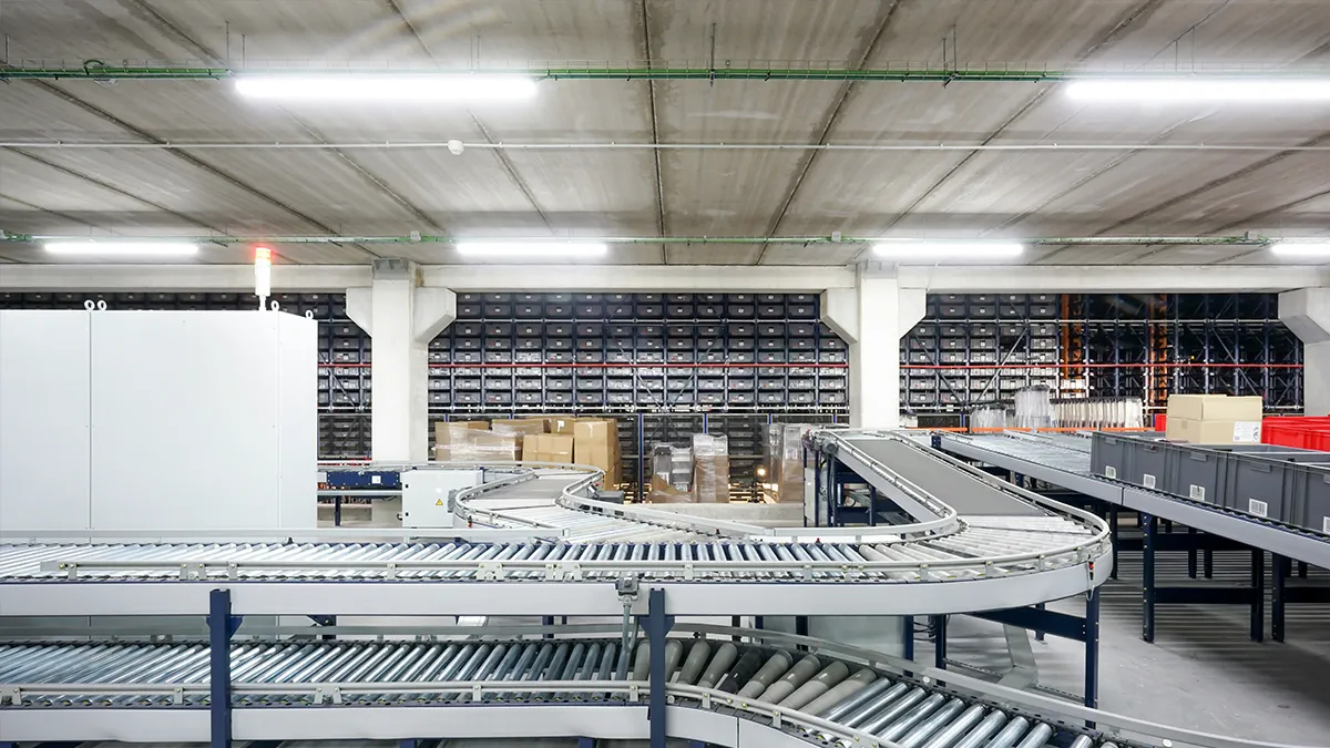
What Is Glare and Why Does It Matter in Industrial Settings?
Glare occurs when a light source — or a highly reflective surface — produces luminance levels that exceed what the human eye can comfortably adapt to in the current viewing context. In industrial facilities, this is more than a comfort issue. It’s a safety and productivity issue.
There are two categories to understand:
Discomfort Glare vs. Disability Glare
Discomfort glare causes annoyance, visual fatigue, and reduced concentration without necessarily impairing vision outright. A worker at a quality-control station who is exposed to a bright fixture at a low angle above the conveyor belt may not “go blind,” but their error rate climbs after two hours.
Disability glare directly reduces visual performance. A forklift operator driving toward a bay door where an unshielded 400W LED fixture is mounted at eye level has a response-time impairment comparable to a blood alcohol content of 0.05%. OSHA incident reports routinely list “inadequate lighting” as a contributing factor — and glare is usually the hidden mechanism.
Industrial Environments with the Highest Glare Risk
- Precision assembly and electronics manufacturing: Workers hold visual tasks at close range; any luminance imbalance in the peripheral field draws attention and degrades focus.
- Quality inspection lines: Detecting surface defects, color deviations, and dimensional tolerances requires controlled, even illumination — not a bright spot flanked by shadow.
- Warehouses with narrow-aisle racking: Fixtures mounted above an aisle can shine directly into the eyes of a picker walking toward them.
- Vehicle maintenance bays: Technicians frequently look upward; fixtures positioned overhead become a direct glare source.
- Offices and control rooms within production facilities: These spaces blend computer screen work with ambient industrial lighting — a combination that requires tight glare control.
Understanding the UGR System
The Unified Glare Rating (UGR) is the international standard metric for quantifying discomfort glare in indoor environments. It was developed by the International Commission on Illumination (CIE) and is embedded in EN 12464-1 (European lighting for workplaces) and ISO 8995-1 (international equivalent). If you’re procuring LED fixtures for a facility that ships into Europe, has ESG reporting requirements, or is applying for LEED/BREEAM certification, UGR compliance isn’t optional — it’s contractual.
How UGR Is Calculated
The UGR formula evaluates the visual impact of each luminaire in the observer’s field of view, factoring in:
- The luminance of each glare source (cd/m²)
- The solid angle subtended by each source
- The position of each source relative to the observer’s line of sight (Guth position index)
- The background luminance of the entire visual field
The result is a dimensionless number, with lower values indicating less glare. The practical UGR scale runs from 10 (imperceptible glare) to 30 (intolerable glare), in steps of 3. Most industrial lighting standards specify a maximum UGR that fixtures in a given space must not exceed.
UGR Limits by Industrial Application
| Space / Task Type | Min. Illuminance (lux) | Max. UGR | Min. CRI |
|---|---|---|---|
| Rough work / raw material storage | 200 lx | 28 | Ra 60 |
| General assembly / production floor | 300 lx | 25 | Ra 80 |
| Medium precision assembly | 500 лк | 22 | Ra 80 |
| Fine precision assembly | 750 lx | 19 | Ra 80 |
| Inspection of very fine detail | 1,000 lx | 16 | Ra 90 |
| Office / control room within plant | 500 лк | 19 | Ra 80 |
| Warehouse aisles / loading docks | 200–300 лк | 25 | Ra 80 |
| Vehicle maintenance bays | 500 лк | 22 | Ra 80 |
Source: EN 12464-1:2021 Table 5.3 – Industrial activities and crafts
A UGR of 19 or below is the threshold for most sedentary visual-intensive tasks. For heavy manufacturing without fine visual demands, UGR 25–28 is generally acceptable. The numbers become binding when your facility holds ISO 9001 or ISO 45001 certifications, which increasingly require documented compliance with workplace lighting standards.
UGR<19 Fixtures: What This Label Actually Means
You’ll frequently see “UGR<19” printed on LED panel and troffer spec sheets. This designation means the fixture, when installed in a reference room of specific dimensions (8m × 6m × 2.8m ceiling height, 70/50/20 reflectances) with a viewing distance of 4H from the wall, produces a tabular UGR value below 19. It is not a universal guarantee — actual UGR in your specific room depends on room geometry, mounting height, fixture spacing, and reflectance values of walls, ceilings, and floor.
This distinction matters for procurement: a fixture with a published UGR<19 rating can still produce unacceptable glare in a low-ceiling space with high-gloss surfaces. Always cross-check with photometric simulation (DIALux or AGi32) before finalizing a specification.
The BUG Rating System for Outdoor and High-Bay Applications
For outdoor industrial spaces and high-bay environments where fixtures project light at steep angles, the IES BUG (Backlight-Uplight-Glare) rating system supplements or replaces UGR as the relevant metric. Mandated by many municipal codes and the IDA (International Dark-Sky Association) model ordinances, BUG ratings quantify:
- B (Backlight): Light projected behind the fixture — relevant for wall-mounted floods and area lights near property boundaries.
- U (Uplight): Light projected upward — the primary cause of sky glow and a common point of municipal code scrutiny.
- G (Glare): High-angle light projected at 60–90° above horizontal — the zone that creates direct discomfort glare for observers at ground level.
Each component is rated on a scale of 0–5, with lower numbers indicating less light pollution and glare. For a typical industrial outdoor application, specifying fixtures with a G-rating of 1 or 2 effectively prevents disability glare at pedestrian and vehicle-operator level.
Physical Mechanisms That Create Glare in LED Fixtures
Not all glare comes from insufficient shielding. Understanding the four physical sources of glare in LED luminaires helps you evaluate product specs critically:
1. High Surface Luminance of LED Arrays
LEDs are point sources with extremely high luminance — often exceeding 1,000,000 cd/m² at the emitter surface. Traditional fluorescent tubes spread luminance over a large area (typically 5,000–15,000 cd/m²). Even a well-diffused LED panel can have visible hot-spots if the diffuser material has insufficient haze.
What to look for: diffuser transmittance ≥ 85% with haze ≥ 95%, or deep-set optics that shield the LED chip below a cutoff angle.
2. Insufficient Shielding Angle
The shielding angle is the angle between the horizontal plane and the line of sight at which the LED source first becomes visible. For most sedentary industrial tasks, a shielding angle of at least 20° is required; for precision work, 30° or more. High-bay UFO fixtures mounted at 8–12 meters often have shielding angles of only 10–15° when viewed from the working plane — especially if the downlight optic is wide.
3. Specular Reflections on Work Surfaces
Veiling reflections occur when a light source is reflected directly off a polished or semi-polished work surface into the observer’s eyes. This is distinct from direct glare and doesn’t show up in UGR calculations. In PCB assembly, metal machining, and wet food-processing lines, specular glare from the work surface can be the primary visual complaint — even when all fixtures are UGR-compliant.
Solution: position fixtures so the specular reflection zone (at the mirror-angle of the viewing direction) is avoided. Polarized lens filters can reduce veiling reflections by 40–70% in high-criticality stations.
4. Excessive Luminance Ratio Between Task and Background
The eye adapts to the average luminance of the visual field. If a worker focuses on a bright inspection surface under a supplementary task light while the surrounding floor is dim, the luminance ratio may exceed 10:1 — triggering constant re-adaptation and fatigue. EN 12464-1 recommends that the luminance ratio between the task area and the immediately surrounding area not exceed 3:1, and between the task area and the remote surround not exceed 10:1.
Selecting Low-Glare LED Fixtures for Industrial Applications
Glare performance should be part of the fixture selection scorecard — alongside lumens per watt, CRI, IP rating, and warranty. Here’s what to evaluate:
High-Bay Fixtures (Factories, Warehouses, 6–20m Ceiling Heights)
- Optic type: Asymmetric or Type III/IV distribution reduces lateral light throw and narrows the glare zone. For narrow aisles, aisle-type optics concentrate light downward without side spill.
- Cutoff classification: Full-cutoff fixtures emit no light above 90° (horizontal) and less than 10% above 80°. This is the default for glare-sensitive warehouse and production environments.
- Lens material: Frosted polycarbonate or opal diffuse glass substantially reduces perceivable surface luminance versus clear covers. Micro-prismatic lenses offer a middle ground — high efficiency with moderate luminance reduction.
- UGR table availability: Reputable manufacturers publish the UGR tabular values for their fixtures across multiple room dimensions. If a manufacturer can’t provide this table, treat it as a red flag.
Linear LED Fixtures (Flush / Suspended, for Lower Ceilings)
- Indirect/direct ratio: Fixtures with 30–40% indirect component illuminate the ceiling and reduce the luminance contrast between fixture and surroundings, lowering perceived glare.
- Opal vs. prismatic diffuser: Opal diffusers produce lower peak luminance at the cost of 5–8% efficiency loss. For UGR<19 applications, the opal option is usually worth the tradeoff.
- Microprism film: Some linear LED luminaires use microprism film that redirects light downward at angles ≤60°, achieving low UGR without sacrificing efficiency.
Task and Supplementary Lighting
For precision assembly stations, dedicated task lighting mounted below the visual field (under-shelf or work-surface-integrated) can deliver 1,000+ lux to the task plane while keeping overhead ambient lighting at 500 lux — reducing luminance ratio stress on the eye. LED task lights with adjustable color temperature (tunable white 4,000–5,000 K) and polarized filters are the standard specification for quality inspection benches.
Layout Strategies to Minimize Glare
Even the best fixtures create glare if mounted incorrectly. Layout decisions that affect glare include:
Mounting Height and Spacing-to-Height Ratio
Higher mounting reduces the angle of the fixture in the observer’s visual field. A fixture mounted at 12m is viewed at a steeper downward angle (and thus farther from the glare zone) than the same fixture at 6m. When ceiling height is constrained, increase the shielding angle of the fixture to compensate.
The SHR (Spacing-to-Height Ratio) also matters: fixtures spaced too far apart create luminance peaks and troughs. A maximum SHR of 1.2–1.5 (depending on beam type) maintains the uniformity ratio (U0 ≥ 0.6) needed to prevent the eye from constantly re-adapting between bright and dark zones — a secondary cause of fatigue.
Fixture Orientation Relative to Viewing Direction
For tasks where workers face a fixed direction (conveyor belts, assembly lines), mounting fixtures parallel to the line of sight — rather than perpendicular — reduces the number of fixtures in the critical glare zone (60–90° above the line of sight in front of the observer). This “end-to-end” orientation is standard practice in European production facilities for exactly this reason.
Zone-Based Illuminance Strategy
Rather than flooding the entire production floor uniformly at 500 lux, consider a tiered approach:
- Ambient layer (overhead): 200–300 lux with UGR<25, providing orientation and movement safety
- Task layer (local): 500–1,000 lux delivered by supplementary task lighting at the point of work
- Accent/emergency layer: low-glare exit and aisle markers
This strategy delivers high task illuminance without pushing overhead fixtures to extreme intensities that compromise glare performance. It also yields 20–35% energy savings versus uniform high-level ambient schemes.
Surface Reflectance: The Silent Glare Multiplier
Ceiling and wall reflectance values have a disproportionate effect on UGR outcomes. EN 12464-1 recommends the following reflectances for industrial spaces:
- Ceiling: 0.70–0.80 (matte white or light gray)
- Walls: 0.50–0.70
- Floor: 0.20–0.40 (light gray, beige)
- Work surfaces: 0.20–0.70 (matte finish preferred over gloss)
A factory with dark gray walls and a black-painted steel ceiling structure creates two problems: it increases the luminance contrast between the fixture and its background (raising perceived glare) and reduces the indirect light component, forcing more fixtures to achieve target illuminance (which increases the number of glare sources).
When planning a lighting retrofit, budgeting for ceiling and wall re-painting with high-reflectance matte paint can reduce fixture count by 15–25% — more than offsetting the paint cost — while simultaneously improving UGR values.
Smart Controls and Glare Management
Intelligent lighting controls add a dynamic layer to glare management:
Daylight Harvesting and Glare Zones
Skylights and clerestory windows introduce natural light, which is generally preferred but can create high-contrast glare zones near glazing. A daylight harvesting system dims overhead LEDs in zones adjacent to windows, maintaining target illuminance without creating a stark contrast between naturally lit and artificially lit areas. Without dimming, the transition zone can have a luminance ratio exceeding 20:1 — well above the 10:1 recommended maximum.
Tunable White for Shift-Based Work
LED color temperature affects perceived brightness and glare sensitivity. Higher CCT (5,000–6,500 K) increases perceived brightness at the same lux level — useful for alertness during night shifts, but it can amplify perceived glare because the eye’s photopic sensitivity curve peaks at shorter wavelengths. Tunable white systems that shift from 5,000 K to 4,000 K during afternoon hours can reduce glare complaints in mixed day/night production facilities without sacrificing illuminance.
Dimming and Scene Control
A DALI-2 or 0-10V dimming system that allows workers to adjust their local task lighting within a defined range (e.g., 50–100%) gives individuals agency over their immediate visual environment. Studies in automotive assembly plants show a 12–18% reduction in visual fatigue complaints when workers have local dimming control at their stations.
Glare Control in Specific Industrial Environments
Metal Fabrication and Machining Shops
Polished metal workpieces and coolant fluid surfaces are highly specular. Ceiling-mounted fixtures with wide beam optics will almost always create veiling reflections at some angle. Solutions: use asymmetric distribution fixtures, position lighting to avoid the specular reflection cone, install polarizing lens filters at inspection stations, and use matte finish work-surface covers where possible.
Производство продуктов питания и напитков
Stainless steel equipment, wet floors, and polished tile walls create pervasive specular reflection. In addition to veiling glare, moisture in the air can cause scattering that raises overall background luminance — reducing effective contrast. Use IP66 or IP69K rated fixtures with sealed optics that maintain a consistent beam pattern even in high-humidity environments. Opal diffused covers are preferred over clear polycarbonate in wet-process areas.
Pharmaceutical and Clean Rooms
ISO 14644 clean room standards require smooth, cleanable surfaces — which typically means high-gloss epoxy floors and white-painted walls. This combination creates high specular reflectance. Recessed LED panels with UGR<19 optics are the standard solution; fixtures are flush-mounted to prevent dust accumulation and minimize protrusion into the field of view. Lux levels of 500–750 with UGR<16 are typical for packaging and inspection areas.
Data Centers and Electrical Control Rooms
Operators monitoring screens require very tight glare control — both from overhead fixtures and from reflections on monitor surfaces. Specify fixtures with UGR<16 (the recommended limit for screen-based tasks per EN 12464-1), use indirect-dominant distributions (70% uplight), and ensure fixture positions don’t coincide with specular reflection angles of the monitors. Anti-glare screen protectors and matte desk surfaces are complementary measures.
Measuring and Verifying Glare in Existing Installations
If workers are complaining about glare in an existing facility, the diagnosis follows a structured process:
- Identify the complaint zone: Note the specific workstations, viewing directions, and times of day when glare is worst.
- Measure background luminance: Use a calibrated luminance meter (e.g., Konica Minolta LS-150) to measure the average luminance of the visual field.
- Identify the glare source(s): Photograph the field of view from the worker’s position — luminance camera images (HDR photography or dedicated imaging photometers) can map luminance distribution across the visual field and immediately identify the glare sources.
- Calculate or estimate UGR: If photometric data is available for the fixtures, use DIALux simulation to recalculate UGR with the actual room parameters.
- Apply targeted remedies: Options include adding louvers or diffusers to existing fixtures, repositioning fixtures to increase the shielding angle, adjusting fixture output via dimming, adding indirect uplighting to raise background luminance, or replacing fixtures with low-glare alternatives.
Return on Investment: The Cost of Getting Glare Control Right
The business case for investing in low-glare fixtures includes factors that standard energy-savings ROI models miss:
- Quality inspection accuracy: A study at a European automotive parts manufacturer found that reducing glare from UGR 25 to UGR 19 in an inspection line reduced the defect-escape rate by 3.2% — equivalent to avoiding 640 warranty returns per year on a production run of 20,000 units.
- Absenteeism and eye strain: Chronic visual discomfort from glare is a recognized cause of headaches and eye strain. Facilities reporting reduced glare after LED retrofits consistently note a 5–15% reduction in glare-related health complaints in post-occupancy surveys.
- Reduced re-inspection costs: In pharmaceutical manufacturing, a single batch rejection due to missed inspection defects can cost $50,000–$200,000. Proper lighting control reduces the risk, even if ROI quantification is difficult.
- Regulatory compliance: Failure to meet EN 12464-1 or OSHA 1910.303 lighting requirements in an incident investigation can lead to citations, increased insurance premiums, and liability exposure. Compliant UGR values are documented protection.
When selecting between a standard UFO high-bay at $45/unit and a low-glare variant with a frosted optic and UGR tabular data at $65/unit, the $20 premium is typically recovered within the first year through quality and attendance improvements in precision manufacturing environments.
Часто задаваемые вопросы
What UGR value do I need for a production floor?
For general manufacturing tasks, the EN 12464-1 standard specifies a maximum UGR of 25. For medium to high precision assembly, UGR 22 is required, and for fine precision work or inspection tasks, UGR 19 or lower applies. When in doubt, target UGR<22 as a default for any production environment — it provides a comfortable buffer without significantly constraining fixture selection.
Can I retrofit existing fixtures with anti-glare accessories?
Yes. Several options are available: prismatic diffuser panels can be added to the underside of linear LED fixtures, louver grids can be clipped onto troffers or panels to increase the cutoff angle, and frosted polycarbonate sleeves can be fitted over high-bay UFO fixtures. These solutions typically reduce fixture efficacy by 10–20%, so verify that the modified output still meets your illuminance targets. For high-ceiling industrial fixtures, factory-supplied optical attachments from the original manufacturer are preferable to aftermarket accessories that may not have been tested together with the fixture.
Is UGR the same as glare index (GI) or discomfort glare rating (DGR)?
These are related but distinct metrics. UGR (CIE Publication 117) is the current international standard for indoor discomfort glare. The earlier British Glare Index (BGI) used a different formula and scale. DGR is an older term sometimes used informally. For new industrial projects and international compliance, UGR is the relevant metric — ensure your photometric simulation software outputs UGR values, not older glare indices.
How does mounting height affect UGR in a high-bay installation?
Increasing mounting height reduces the vertical angle at which the fixture appears in the observer’s visual field — moving it farther from the critical glare zone (60–90° above horizontal). As a rule of thumb, doubling the mounting height from 6m to 12m reduces UGR by approximately 3–5 points for the same fixture. This is why 12m+ ceiling heights offer significant natural glare relief compared to 6–8m industrial spaces.
What’s the difference between glare control and anti-glare coatings on LED modules?
Anti-glare coatings (often marketed as “matte” or “anti-reflective” surfaces on LED drivers or enclosures) primarily address specular reflection from the fixture body — not from the LED light output itself. True glare control is a function of optics: shielding angles, diffuser haze, and beam distribution. Don’t confuse a matte-painted fixture housing with a genuinely low-UGR optical design.
Do smart controls improve UGR?
Smart controls don’t change the inherent UGR of a fixture — a fixture’s UGR is determined by its photometry. However, dimming controls can reduce the luminous output of sources that are too bright for a given environment, effectively reducing the practical UGR experienced by workers. A fixture at 60% output typically produces a UGR approximately 2–3 points lower than the same fixture at 100%. This is a useful lever for fine-tuning glare performance after installation without replacing hardware.
Where can I find photometric files (IES/LDT) to simulate UGR in my facility?
Reputable LED manufacturers provide IES (North American standard) or LDT (European standard) photometric files for all their commercial and industrial products. These files can be imported into DIALux, AGi32, or Relux simulation software. When evaluating new fixtures, request the photometric files and the UGR tabular values as part of your standard RFQ documentation. If a supplier can’t provide these files, the product hasn’t been properly characterized — and you have no basis for verifying UGR compliance before purchase.
Основные выводы
Glare control isn’t a feature to add after a lighting project is complete — it’s a design requirement that needs to be specified before a single fixture is ordered. The UGR framework gives you a standardized, internationally recognized way to specify, simulate, and verify glare performance. The BUG rating system extends this to outdoor and high-ceiling environments where traditional UGR calculations don’t fully apply.
The most effective approach is to combine fixture-level specifications (shielding angle, diffuser type, UGR table), layout decisions (mounting height, fixture orientation, zone layering), and surface reflectance planning into a cohesive photometric design — then verify with simulation software before finalizing.
For factories, warehouses, and manufacturing plants looking to upgrade their lighting, addressing glare as part of the LED retrofit process — rather than treating it as an afterthought — consistently delivers better outcomes on quality, worker wellbeing, and regulatory compliance. The incremental cost of specifying low-glare optics is modest; the cost of ignoring glare shows up quietly in inspection errors, fatigue complaints, and liability exposure for years afterward.
To explore Recolux LED’s full range of low-UGR industrial luminaires — including high-bay UFO fixtures with frosted optics, linear LED troffers with microprism diffusers, and customizable task lighting solutions — contact our technical sales team for a photometric simulation review of your facility.